Reverse Sensor of Car Parking
- electromagics89
- Nov 26, 2023
- 2 min read
Updated: Nov 30, 2023
While Parking the vehicle the driver Must be more cautious since he can't see the rear of the vehicle while Parking or taking back side, assuming there is any deterrent and ran over it very well may be get harm to the vehicle. Our venture will assist the individual in the driving seat and give with disturbing in the event that there is any obstruction or a wall while stopping or while driving backward.
Block diagram for reverse sensor of car
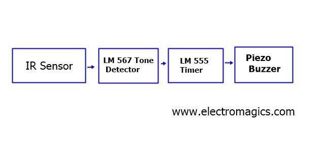
The IR sensor will recognize the impediment with in 100cm, on the off chance that there is any obstruction it will detect and give data to the tone finder which will empower the LM555 clock to produce a PWM for the signal. The LM555 will produce the beat which assists with humming the ringer so driver can comprehend that there is a hindrance.
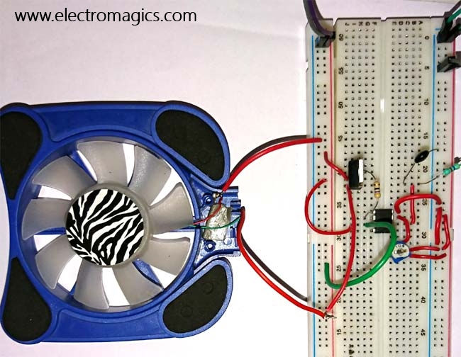
Circuit diagram of Reverse Sensor of Car Parking

Explanation of Circuit Diagram
The Reverse sensor light inventory is given to the 7805 controller to give 5v to the remainder of the circuit. The diode D6 is utilized to take out the opposite current and wrong stock extremity.
At the point when the vehicle is driving backward the vehicle battery will give DC supply the opposite light marker at the rear of the vehicle when this supply came to the converse light pointer the circuit will have the power supply.7805 will manage the DC voltage to 5V and provide for the IR Sensors through the semiconductor with 20 KHz tweaking recurrence of the LM567 (TONE Locator) accessible at Pin5. The resistor R1 will opposes the IR senor current. As of now the pin8 of LM567 is high which will empower the LM555 clock working in astable multivibrator mode. The result of the clock is empowered which can be guaranteed by the Drove (flickering) and furthermore ringer will blares at decided rate given by the resistors R6, R7 and capacitor C7. The clock yield likewise is given to the light through a semiconductor. The light will squint as an advance notice signal in view of the PWM signal created by the clock, semiconductor will fill in as a switch and resistor R10 will restrict the current. This condition is kept up with until the 20 KHz signal is gotten by the pin3 of the LM567.
The above condition is when there is no obstruction in the way of the vehicle while taking opposite. In the event that there is an obstruction the IR bar will emanate back to the IR sensor and the 20KHz regulated signal is given to the pin3 of LM567 through photograph Darlington semiconductor, as of now the pin8 of the LM567 is gone to low and furthermore gets locked to distinguish the 20Khz sign. By this the LM555 is turned low and crippled by this the drove will remain lighting and ringer utters the persistent sound to alarm the driver.
For more Electronics project like


Comments